Adapting a Sherline

Rotary Table for CNC

When I acquired my Sherline table top Mill I also picked up a #3700 rotary table for it. That was back in 1999 and, at the time, neither Sherline, or anyone else, offered a CNC version of it. While I had purchased a CNC 'kit' from Flashcut CNC for the mill there was nothing similar for the rotary table. I remember seeing something once that implied that you couldn't do a CNC conversion on the original table.


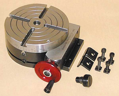
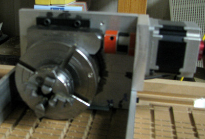
Above: The Sherline 3700
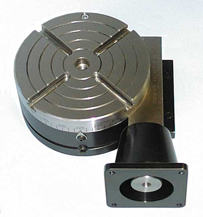
Right: The Sherline 3700 CNC version with a NEMA 23 motor mount.


I had a project in mind that required a rotary axis for my CNC machine. It required me to be able to machine a 24 inch long piece of material almost 4 inches in diameter.  Considering that I only have 4 5/8 in clearance under the gantry of the CNC machine it was going to be a challenge. That height is further reduced to 4 1/8 inch since I've got a vacuum table mounted on the work surface that I really don't want to remove. I figured that the same methods that were used to couple the NEMA 23 motors to the feed screws of the CNC machine would work for the 3700. So I worked up the following design. There are three components shown below. The 3700 mounting plate and NEMA23 motor mount, the Tailstock, and the full assembly.

The images below link to 3d pdf files, click on it if you want to be able to rotate the image around and examine it from other angles. (Note, the 3d.pdf file opens in a new window. If you have problems with the 3d feature you may have to upgrade to the latest version of Adobe Reader).


First The Nema 23 mounting plate is an adaption of the one used on the CNC machine. The only significant modification is that the motor winds up covering the bolts that hold the motor mount to the plate that the 3700 table is mounted on. That plate, as well as the motor mount are both .5 in thick aluminum. That thickness was chosen to give me a rigid right angle mount without needing corner braces. There's really not room for them. I also wanted to be able to mount the 3700, with the CNC adapter, back on my Mill should I need to do some rotary axis work there. The 3700 is mounted so that with the plate on edge it is right at the bottom edge of the plate and the worm drive axis is at a right angle. I added a thrust bearing between the 3700 worm drive and the LoveJoy coupling where the handwheel would have been.

To support the stock at the other end I modified the drive screw bearing block design to mount a .5 inch bearing with it's center aligned with the center of the 3700 table. At the 3700 end I found a 4 jaw self centering chuck designed to fit a Taig lathe. It happens that the 3700 center bore is threaded to fit such a chuck. My stock is mounted using flanges and pieces of .5 in rod that hold it between the bearing on the tailstock end and the chuck on the 3700 end.

The last piece of the assembly is a pair of .25 x 2 aluminum bars that hold the 3700 and the tailstock in alignment. Additional peices of  the same stock are used to make mounting tabs to mount the assembly to my CNC machine table. Not shown in the drawing above is a modification that attaches the mounting tabs at the end of the plates instead of to the bottom. That saves me .25 inch in clearance. The other 'trick' is that the CNC gantry only has to clear the tailstock assembly and not the 3700 on the mounting plate.

Here are some pictures of the finished product.


There are some challenges to using a rotary table in a CNC machine. One is locating the table in relation to the path of the cutting bit. The presumption is that the long axis of the CNC machine is perfectly aligned with the rotational axis of the stock. Another is to be able to locate the center of the stock. Finally, pecular to the work I am doing, to be able to set the zero degree point of the form that is carrying the stock reliably.

To locate the axis I scribed alignment marks on the tailstock and the 3700 mounting plate that correspond the the center of the axis. Mounting a scribe point, or in my case a very sharp V bit, in my router allows me to verify the position of the rotational axis at both ends. That location also fixes the Y axis zero location. Locating the center of the stock is simple since, once measured, the top edge of the tailstock plate is a fixed distance from the centerline of the bearing.

The project I'm undertaking involves making a form which is first used to bend sheets of hot plastic. Once several sheets are bent up, the form is mounted on the rotary axis and the sheets are bolted in place and machined to size. Since the form is removed from the rotary axis I needed a way to locate the zero degree position on the form. [A zero on the rotary table could be used only if the form was indexed to the table]. To do that I simply drilled a hole (using the CNC machine, naturally) and inserted a second Sharp V bit in the hole. When the tips of the 2 Vbits align I know I'm at zero. Sample pictures follow.


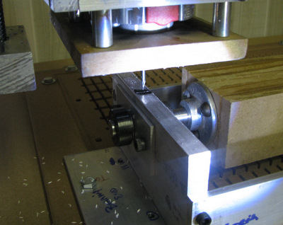
checking and setting Y=0

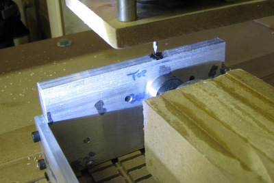
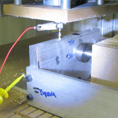
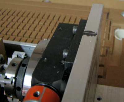
Above: Alignment mark on the 3700 end
Right: setting Z based on tailstock height

Above and Right setting rotational axis to zero

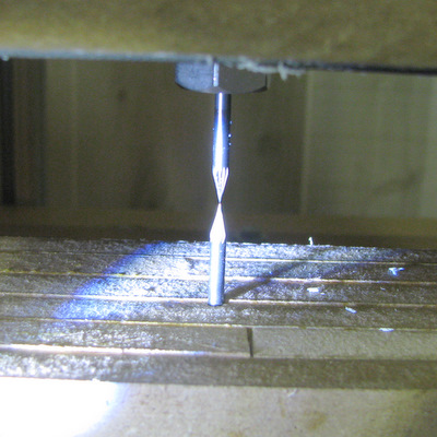
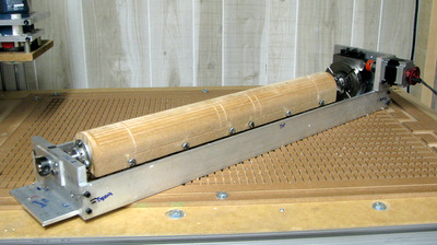
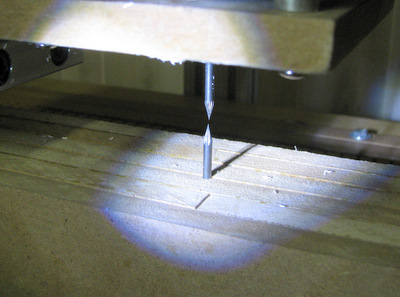
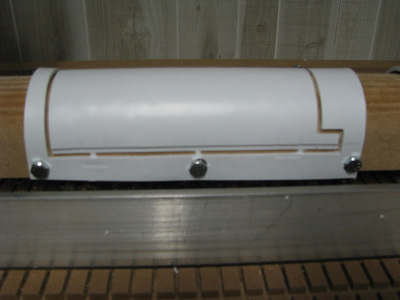
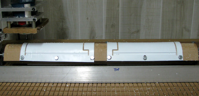
Above and Right: bent plastic sheet being machined.

The intrepid among you are welcome to download autocad .dwg and adobe .pdf files of the parts I designed. If you are curious, and want to see what that part turns into please visit my R2D2 website.


Home