Vacuum Hold Down

Second Pass

So if at first you don't succeed, try again! I fixed the positioning/repeatability problems I was having on my CNC machine. That had caused some of the slots and holes on my first vacuum table to be out of position. I has also tried to build that first one a little too large. I couldn't machine all of it at one time. That's not impossible to do, it just makes the job harder.

For my second pass my target work area was 20x30 inches. (actually bigger than the first table by 1 inch) but the table overall is only 24x36. I cut the table base out of a piece of 1/2 inch MDF. (see my notes below on do-overs!). Rather than rely on a CAM program to translate my Autocad slots into gcode I wrote some of my own. It's really very simple, particularly for lots of straight cuts. Finally, I had to bring the vacuum feed in from under the table rather than end feed the way I did in the first pass to accommodate the shorter table size.


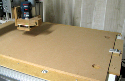
Clamp the MDF to the CNC table while you cut the
mounting holes and the vacuum inlet ports.

Cut the mounting holes and vacuum ports into the CNC
table. (ouch!)

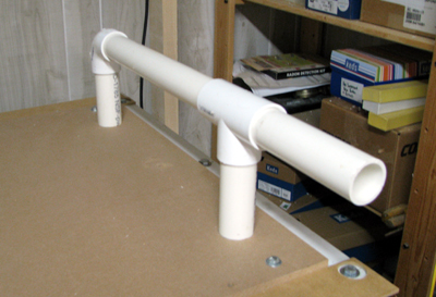
Here's what the vacuum plumbing looks like. This goes
under the table so don't glue the pipes together!

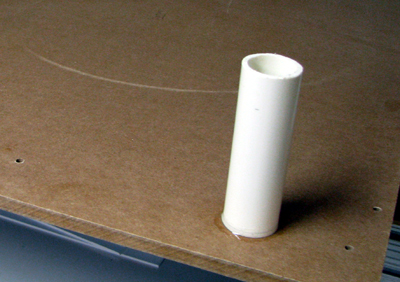
Just glue the short risers into the MDF. Make the holes
in the CNC table oversize to clear the glue bead.

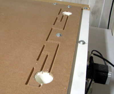
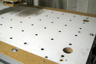
MDF now bolted onto CNC table and vacuum ports cut.
See my notes below on do-overs. Those slots are too small.

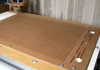
vertical slots cut into the MDF

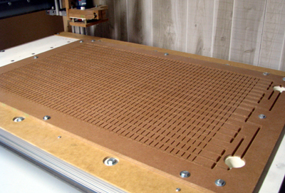
And now the horizontal slots cut as well.

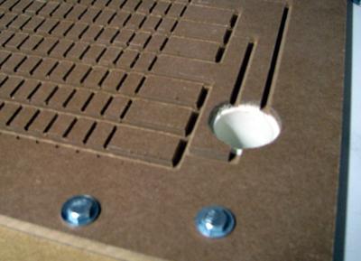
closeup of feed slots and H&V grid slots.

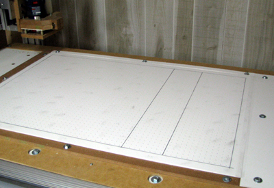
shown here the working surface is a piece of expanded PVC
sheeting. My next set of working surfaces will be tempered
hardboard. (It's cheaper!) - the holes are .1 dia on .5 centers

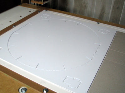
Typical cut of a 20x20 piece of styrene.

Some comments on things I'd do differently next time:
MDF is notorious for being porous. I sealed mine on top and bottom (and edges!) before cutting with shellac.  I Cut
it  50% with alcohol, it goes on easily with a roller, you can make several coats, it's absorbed into the surface so there's no buildup, and it dries quickly. Once it's dry it can be sanded smooth. I painted my CNC table which was a mistake. The paint built up in some locations more than others and ruined the flatness of the surface. It's not clear from the CNC table picture, but the mounting holes I drilled to hold the vacuum table down have threaded inserts in them. I did that because the inserts could be driven in from above. While it worked just fine, it was also a mistake. When you drive a threaded insert into MDF the edges of the MDF around the hole rise up slightly. If I had used tee-nuts the way I did on the original design that would not have happened. If you look closely you can see where I used a razor blade to attempt to trim off the edges of the hole. This all affects the flatness of the vacuum table, and not in a good way!

There are two vacuum inlets because the gantry feed screw runs down the middle of the table. I wanted a symmetrical vacuum feed to keep both top and bottom edges of the table supplied with an equal feed. The feed slots shown above are too small. If you compare the cross section area of the feed pipes, the feed slots and the horizontal slots there was a big mismatch at the feed slots. I had to make them significantly wider. The problem is that you have to leave some material behind to hold up the material that covers the feed slot. Without enough support it will fold down into the slots. When I remake this design next I'll use a piece of 3/4 inch MDF instead of the 1/2 inch I used here. It will permit me to make deeper feed slots.

Aside: I could also have brought the vacuum inlets in from the top/end rather than from the underside. The mount I made for my Bosch Colt, however, extends out an additional 4 inches in the X direction beyond the centerline of the bit. That would make for a difficult clearance problem so I opted to come in from below. I could have put the feed at the opposite end, the way I did with the first table, but then I'd have problems with gantry clearance. Those would not be insurmountable, just a PITA when the gantry is in the home position.

A word about workflow:
I used my own Gcode to cut the horizontal and vertical slots as well as drill the field of holes. It is much more efficient than the code generated by most CAM programs I've seen. (aside - If you are using a $5000 piece of CAM software I haven't seen it. for that price it will most likely work very well. But it's out of my budget range). The grid of holes is offset a 1/4 of an inch so that the holes are in the center points of a 1/2 inch grid. This enables me to place the edges of the parts for cutting on the 1/2 inch grid knowing that the cut lines will not expose the vacuum holes. Some cuts, of course will, it can't be helped, but it's good to know when you are cutting into your vacuum lines or not. I place a drop out grid on the parts cutting layout drawings to help me position the parts. See the Doc Package for a sample of the grid.

I've put together a documents package that contains
Vac Table Autocad Drawing and Gcode Files:
vtbl.composite.dwg - all components of the table (broken out separately below)
vtbl.hslots.dwg - horizontal slot pattern
vtbl.vslots.dwg - vertical slot pattern
vtbl.orig.vac.ports.dwg - the original vac ports drawing (as in the pix)
vtbl.xpnd.vac.ports.dwg - the expanded vac ports (see text)
vtbl.o.hslots.vports.dwg - orig vac ports + horiz slots
vtbl.x.hslots.vports.dwg - expanded vac ports + horiz slots
vtbl.surface.outline - Work Surface and Vac Port Cover
vtbl.grid.dwg - parts placement grid drawing
cut.vslots.ngc - gcode to cut vertical slot pattern
grid.drl.ngc - gcode to drill hole pattern in sacrificial board.


Home