Diagnostics
How
do you really know your cuts are coming out in the right place?
I
wrote a little test program. Or rather, I wrote a program that
generates Gcode that can be used for a test. It draws the same pattern
in an x by y grid. You tell the program how big to make the pattern (size), and how big the grid should be in x and y (nx, ny) pattern sets. It writes a Gcode file using the filename, and extension, you give it (filename.ext).
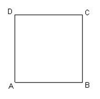
The first pattern drawn/cut is a square.
The first line/cut is from A to B, then from B to C, then from C to D
and finishing with D to A. | 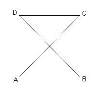
The second pattern drawn/cut is the diagonals of the square.
The first line/cut is from A to C. Followed by a move from C to D,
then a line/cut from D to B. |
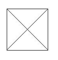
If you were only drawing a single pattern it would now look like this | 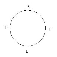
The last pattern is the circle inscribed in the square.
It is drawn/cut as a set of 4 arcs starting witn E to F, then F to G,
G to H and finally H to E |
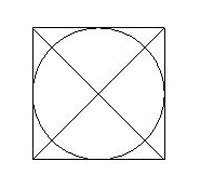
If you were only drawing a single pattern it would now look like this | If you draw multiple copies of the pattern (nx, ny) all
of the squares are drawn first starting at 0,0 and incrementing
first x then y. Then all of the diagonals are drawn, and finally all of
the circles. |
The program is written in Python and
called cnc_test.py. You can download a copy here
along with a sample of the output. Why Python? It's easy to learn.
There are any number of on-line documents and tutorials. Error handling
and type checking/conversion are built into the language making
debugging easier. Although not needed for this program it supports
higher level constructs and has math, image, plotting and drawing
library support. It's open source and available for both Linux and
Windows. Go here for more on Python and links to other sites.
I
also built a pen holder, converting my cnc router into a very expensive
flat bed plotter. Most pen holders are made from a pair of telescoping
tubes. The inner holding the pen the outer mounted to the router. A
spring provides the force to pus the pen against the table surface. I
didn't have any appropriate tubing. But I did have more than a few dead
DVD writers. One was disassembled to yeild a sliding carriage to mount
a pen onto.
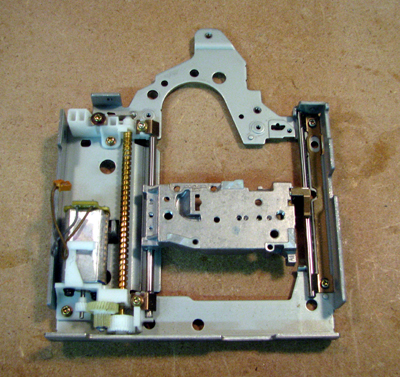
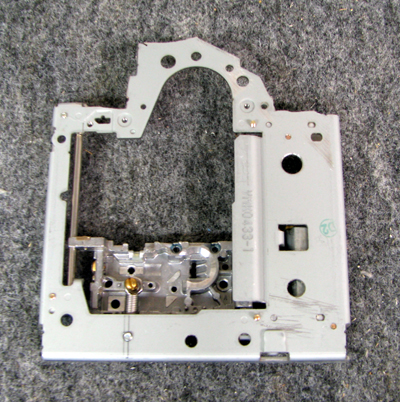
The drive was stripped down and the optics removed from the slide | 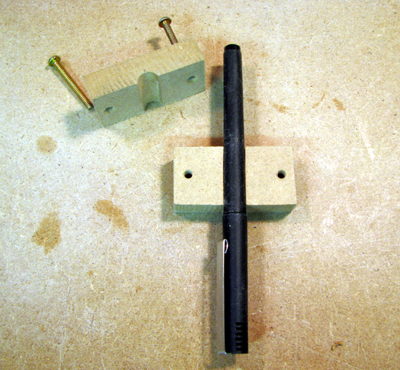
I made a pen mounting block from two pieces of 1/2 inch MDF. |
A spring was mounted on the underside of the slide block to provide
pen force for drawings | 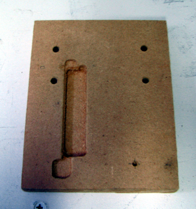
The drive slide isn't flat. I machined a mounting block to accomodate. |
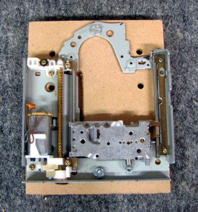
Carriage installed on it's mounting block. | 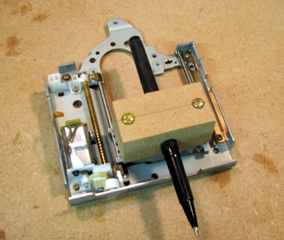
Pen mounting block attached to slide.
I tapped the two holes on the slide to fit the screws that hold the block together |
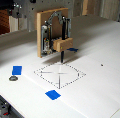 | 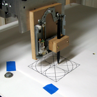 |
The
last two pictures show a single 4 inch diagnostic pattern and then a
2x2 grid of 2 inch patterns being plotted on top. Note that all
the edges
line up with each other and the diagonals of the 2x2 pattern lie on top
of the ones from the 4 inch pattern. All of the circle edged lie on top
of the sides of the squares. Isn't it nice when something works?
Gotchas:
If you look carefully, you'll notice that the pen is not lined up with
the center of the mount. If you compare the pen mount with the router
mount you'll also notice that it's not as deep. The effect is that the
router and the pen cut and draw in different positions. Since most CNC
work involves setting the 0,0 position it usually does not matter. If
you were expecting to draw on the workpiece and then cut it in the same
locations you'll have to modify the pen mount to match your router.
Given the complexity of the above mount, and it's shortcomings, I've designed a second version.
It's based on a stubby version of the sharpie marker which I stumbled across iwhile browsing in an arts supply store.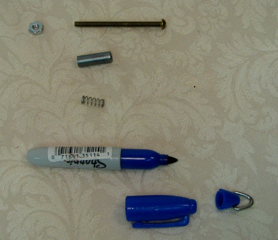 | 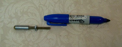
the parts are: (shown to left)
Mini Fine Point "Sharpie" marker - it's about 3.25 in long
6-32 x 2in bolt (1.5 in long might also be ok) and 6-32 nuts
.25 in mounting post, .75 in long comes drilled to accept 6-32 bolt
compression spring, approx .5 long to fit as shown above.
drill a hole in the top of the sharpie cap to fit the 6-32 bolt
use additional nuts (not shown in pix) to attach the cap to the end
of the bolt. The mounting post should fit in your router spindle
The Biggest limitations are: you'll need about 4 in of clearance
and the assembly, because of it's length, isn't all that rigid so accuracy
will suffer. |